|
| Orifice Flanges (Class 600) |
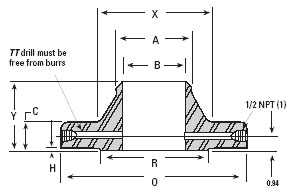
WELDING NECK (2,3) - ANSI B16.36

RAISED FACE
| NOMINAL PIPE SIZE |
OUTSIDE DIA. OF FLANGE
O |
THICKNESS OF FLANGE, (4) MIN. C |
OUTSIDE DIA. OF RAISED FACE R |
LENGTH THROUGH HUB (4) Y |
HEIGHT OF RAISED FACE H |
| 1 |
4.88 |
1.50 |
2.00 |
3.25 |
0.06 |
| 1.5 |
6.12 |
1.50 |
2.88 |
3.38 |
0.06 |
| 2 |
6.50 |
1.50 |
3.62 |
3.38 |
0.06 |
| 2.5 |
7.50 |
1.50 |
4.12 |
3.50 |
0.06 |
| 3 |
8.25 |
1.50 |
5.00 |
3.50 |
0.06 |
| 4 |
10.75 |
1.50 |
6.19 |
4.00 |
0.25 |
| 6 |
14.00 |
1.88 |
8.50 |
4.62 |
0.25 |
| 8 |
16.50 |
2.19 |
10.62 |
5.25 |
0.25 |
| 10 |
20.00 |
2.50 |
12.75 |
6.00 |
0.25 |
| 12 |
22.00 |
2.62 |
15.00 |
6.12 |
0.25 |
| 14 |
23.75 |
2.75 |
16.25 |
6.50 |
0.25 |
| 16 |
27.00 |
3.00 |
18.50 |
7.00 |
0.25 |
| 18 |
29.25 |
3.25 |
21.00 |
7.25 |
0.25 |
| 20 |
32.00 |
3.50 |
23.00 |
7.50 |
0.25 |
| 24 |
37.00 |
4.00 |
27.25 |
8.00 |
0.25 |
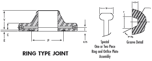
| RING TYPE JOINT |
NOMINAL
PIPE
SIZE |
GROOVE NUMBER |
PITCH DIA.
P |
GROOVE DEPTH
E |
GROOVE WIDTH
F |
RADIUS AT BOTTOM R max |
SPECIAL
OVAL RING HEIGHT W |
| 1 |
R16 |
2.000 |
0.250 |
0.344 |
0.03 |
1.00 |
| 1.5 |
R20 |
2.688 |
0.250 |
0.344 |
0.03 |
1.00 |
| 2 |
R23 |
3.250 |
0.312 |
0.469 |
0.03 |
1.06 |
| 2.5 |
R26 |
4.000 |
0.312 |
0.469 |
0.03 |
1.06 |
| 3 |
R31 |
4.875 |
0.312 |
0.469 |
0.03 |
1.06 |
| 4 |
R37 |
5.875 |
0.312 |
0.469 |
0.03 |
1.06 |
| 6 |
R45 |
8.312 |
0.312 |
0.469 |
0.03 |
1.06 |
| 8 |
R49 |
10.625 |
0.312 |
0.469 |
0.03 |
1.06 |
| 10 |
R53 |
12.750 |
0.312 |
0.469 |
0.03 |
1.06 |
| 12 |
R57 |
15.000 |
0.312 |
0.469 |
0.03 |
1.06 |
| 14 |
R61 |
16.500 |
0.312 |
0.469 |
0.03 |
1.06 |
| 16 |
R65 |
18.500 |
0.312 |
0.469 |
0.03 |
1.19 |
| 18 |
R69 |
21.000 |
0.312 |
0.469 |
0.03 |
1.19 |
| 20 |
R73 |
23.000 |
0.375 |
0.531 |
0.60 |
1.25 |
| 24 |
R77 |
27.250 |
0.438 |
0.656 |
0.60 |
1.44 |
GENERAL NOTE: Dimensions are in inches.
NOTES:
(1) Other NPT sizes may be furnished if required.
(2) Weldneck flanges NPS 3 and smaller are identical to Class 300 flanges except for bolting
and may be used for such service.
(3) All other dimensions are in accordance with ASME/ANSI B16.5.
(4) 0.06 in. height of raised face in NPS 1-3 is included in dimensions C and Y.
WELDING NECK (2,3) - ANSI B16.36

NOMINAL
PIPE
SIZE |
DIA.
OF
HUB
X |
HUB DIA.
BEGINNING
OF CHAMFER
A |
BORE
B |
DIA. OF
PRESSURE
CONNECTION
TT |
| 1 |
2.12 |
1.32 |
SEE
NOTE
(7) |
0.25 |
| 1.5 |
2.75 |
1.90 |
0.25 |
| 2 |
3.31 |
2.38 |
0.25 |
| 2.5 |
3.94 |
2.88 |
0.25 |
| 3 |
4.62 |
3.50 |
0.38 |
| 4 |
6.00 |
4.50 |
0.50 |
| 6 |
8.75 |
6.63 |
0.50 |
| 8 |
10.75 |
8.63 |
0.50 |
| 10 |
13.50 |
10.75 |
0.50 |
| 12 |
15.75 |
12.75 |
0.50 |
| 14 |
17.00 |
14.00 |
0.50 |
| 16 |
19.50 |
16.00 |
0.50 |
| 18 |
21.50 |
18.00 |
0.50 |
| 20 |
24.00 |
20.00 |
0.50 |
| 24 |
28.25 |
24.00 |
0.50 |
| DRILLING TEMPLATE |
| NOMINAL |
DIA. OF
BOLT
CIRCLE |
NO.
OF
HOLES |
DIA. OF HOLES |
DIA. OF BOLTS |
| PIPE SIZE |
RAISED FACE |
RING JOINT |
| 1 |
3.50 |
4 |
0.69 |
0.75 |
0.62 |
| 1.5 |
4.50 |
4 |
0.88 |
0.88 |
0.75 |
| 2 |
5.00 |
8 |
0.75 |
0.75 |
0.62 |
| 2.5 |
5.88 |
8 |
0.88 |
0.88 |
0.75 |
| 3 |
6.62 |
8 |
0.88 |
0.88 |
0.75 |
| 4 |
8.50 |
8 |
1.00 |
1.00 |
0.88 |
| 6 |
11.50 |
12 |
1.12 |
1.12 |
1.00 |
| 8 |
13.75 |
12 |
1.25 |
1.25 |
1.12 |
| 10 |
17.00 |
16 |
1.38 |
1.38 |
1.25 |
| 12 |
19.25 |
20 |
1.38 |
1.38 |
1.25 |
| 14 |
20.75 |
20 |
1.50 |
1.50 |
1.38 |
| 16 |
23.75 |
20 |
1.62 |
1.62 |
1.50 |
| 18 |
25.75 |
20 |
1.75 |
1.75 |
1.62 |
| 20 |
28.50 |
24 |
1.75 |
1.75 |
1.62 |
| 24 |
33.00 |
24 |
2.00 |
2.00 |
1.88 |
LENGTH OF
STUD BOLTS
[(5), (6)] |
NOMINAL PIPE
SIZE |
|
| RAISED FACE |
RING JOINT |
| 5.00 |
5.50 |
1 |
| 5.25 |
5.50 |
1.5 |
| 5.00 |
5.50 |
2 |
| 5.25 |
5.75 |
2.5 |
| 5.25 |
5.75 |
3 |
| 6.00 |
6.50 |
4 |
| 7.00 |
7.50 |
6 |
| 7.75 |
8.25 |
8 |
| 8.75 |
9.25 |
10 |
| 9.00 |
9.50 |
12 |
| 9.50 |
10.00 |
14 |
| 10.25 |
10.75 |
16 |
| 11.00 |
11.50 |
18 |
| 11.75 |
12.50 |
20 |
| 13.25 |
13.75 |
24 |
Notes: (cont'd)
(5) Bolt lengths for raised face flanges include allowance for orifice and gasket thickness of 0.25 in. for NPS 1-10, 0.75 in. for NPS 12-18, and 0.88 in. for NPS 20.
(6) In conformance with ASME/ANSI B16.5, stud bolt lengths do not include point heights.
(7) Bore is to be specified by the purchaser.
(8) Ring joint flanges in NPS 24* will require an angular meter tap.
ORIFICE FLANGES ARE ALSO AVAILABLE IN
CLASSES 400, 900, 1500 & 2500. |
|
|
|
